Fiber Optic Patch Cord Polishing Method
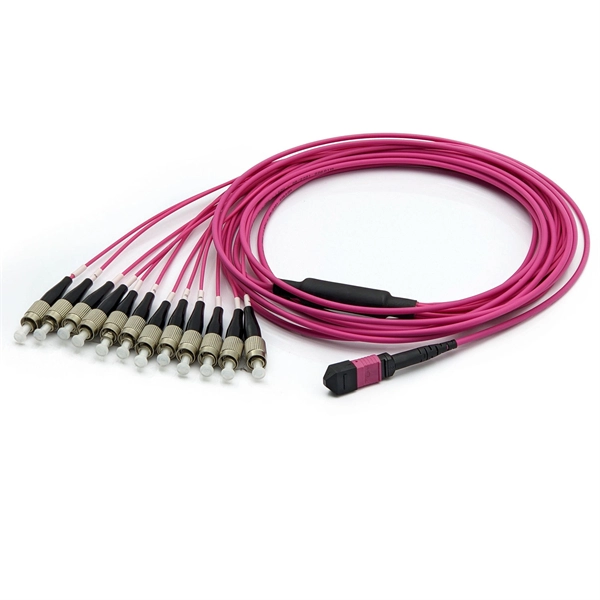
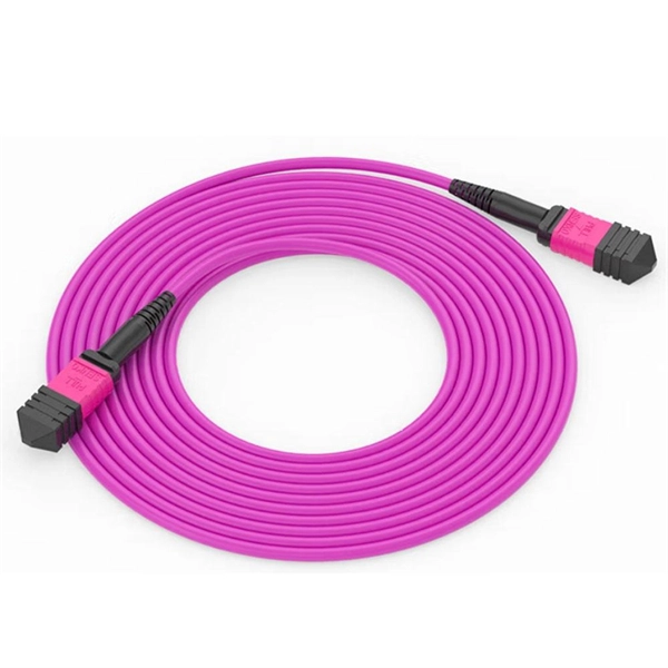
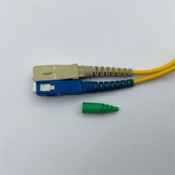
High-quality fiber optic patch cord polishing requires precise multi-step procedures, controlled pressure, speed, and cleaning to ensure optimal end-face geometry and low insertion/return loss.Tools and ConsumablesTo polish fiber optic patch cords effectively, you need:Polishing machine capable of controlling pressure, speed, and timePolish pads (hard and soft) for shaping and finishingLapping/polish films with progressively finer grit (e.g., silicon carbide, diamond, silicon dioxide)Polish jig/fixture to hold connectors at correct angles (especially 8° for APC connectors)Polish oil for lubricationFiber cutting pen for precise fiber trimmingCleaning supplies: distilled water, 99% isopropyl alcohol, lint-free wipes, and compressed airInspection equipment: fiber microscope and interferometer for end-face geometry measurement .Polishing ProcessFiber Preparation: Remove the ferrule from the oven, allow it to cool, and cut the fiber to the correct length using a fiber cutter .Epoxy Removal and Angle Generation: Remove excess epoxy and, for APC connectors, set the 8° angle using the polishing fixture .Geometry Shaping: Refine the ferrule shape, radius, and initial fiber height using coarse polish films and pads .Fiber Height Control: Fine-tune the fiber protrusion to ensure proper physical contact between connectors .Final Optical Finish: Use progressively finer lapping films to achieve a mirror-like, defect-free end-face .Cleaning Between Steps: Thoroughly clean the connector end-face and fixture after each step to prevent contamination from larger grit particles .Best PracticesAutomated vs Manual Polishing: Automated polishing ensures consistent pressure, speed, and timing, which is critical for achieving uniform 3D end-face geometry and low IL/RL, whereas manual polishing is more prone to variability .Process Control: Adjust pressure, speed, and polishing time carefully; improper settings can damage the polishing film or produce substandard end-faces .Inspection: After polishing, inspect the end-face under a microscope and, if available, use interferometry to measure radius of curvature, apex offset, and fiber height .Connector Types: Techniques vary slightly for UPC (flat) vs APC (angled) connectors, with APC requiring precise angle control to minimize return loss .Quality AssurancePerform insertion loss (IL) and return loss (RL) testing on every batch to ensure optical performance meets standards .Maintain a clean environment and use lint-free wipes and alcohol to prevent contamination.Follow multi-step polishing sequences with progressively finer films to achieve stable geometry and mirror-like end-faces suitable for high-speed telecom, FTTH, and data center applications . By adhering to these techniques and best practices, fiber optic patch cords can achieve low insertion loss, high return loss, and reliable long-term performance in optical networks.