Construction steps for direct-buried optical cable lines
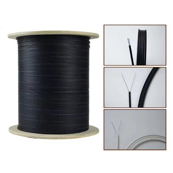
Direct-buried optical cables are installed by careful planning, trenching or plowing, cable placement with proper handling, protective bedding, backfilling, and marking for long-term reliability.1. Planning and Site PreparationBefore construction begins, conduct a site survey to assess soil conditions, terrain, and existing underground utilities. Define the cable route and access points, avoiding tight bends and unnecessary detours, and obtain all required permits and right-of-way approvals . Determine cable lengths based on splice locations and add sufficient slack for splicing and future maintenance . Safety planning is critical: all personnel should be familiar with OSHA regulations and company safety procedures for direct-buried cable operations .2. Cable SelectionChoose the appropriate direct-burial cable type based on environmental and mechanical risks:Loose-tube, gel-filled or gel-free for long outdoor runs.Armored cables with corrugated steel for high-risk areas like road crossings or rocky soil.Tight-buffered or breakout-style for near-building terminations .3. Trenching or PlowingTrenching: Hand or machine-dug trenches are used for precise placement, multiple cables, or complex terrain. Trenches allow controlled bedding and installation of warning systems .Plowing: Suitable for long, linear rural routes. A plow opens a narrow slot and lays the cable in a single pass, though with less control over bedding .4. Cable Handling and PlacementInspect cable reels for damage before installation and protect them from environmental or vandalism risks .Use a figure-eight configuration when unrolling cable to prevent kinking or twisting. Avoid coiling in a continuous direction for lengths over 30 meters (100 ft), .Maintain minimum bend radius and maximum pulling tension as specified by the manufacturer to prevent long-term signal degradation .5. Bedding and BackfillPlace 2–4 inches of fine sand or screened bedding under and over the cable to cushion it and reduce rock penetration risk .Backfill the trench carefully to avoid crushing the cable. In high-risk areas, use armored cable or rodent-resistant jackets.6. Warning Systems and MarkersInstall bright warning tape 6–12 inches above the cable to alert future excavators .Include a tracer wire along the cable route, accessible at handholes, to facilitate future location without excavation.7. Separation and SafetyMaintain minimum horizontal and vertical clearances from electrical conductors according to local codes to prevent induced currents and simplify maintenance .Use handholes or manholes at road crossings, intersections, and building entrances for easier access and protection against concentrated loads .8. Splicing, Termination, and TestingLocate and mark splice points in advance. Prepare each position as the cable approaches to minimize open-hole hazards .Perform splicing and termination according to manufacturer specifications.Conduct optical testing to verify signal integrity and ensure no damage occurred during installation .9. Final Inspection and DocumentationVerify that all cables are properly buried, protected, and marked.Document the installation route, splice points, and any deviations for future maintenance and troubleshooting. By following these steps, direct-buried optical cables can be installed safely and reliably, ensuring long-term network performance and minimizing the risk of accidental damage or signal degradation .