Low-voltage switchgear busbar configuration
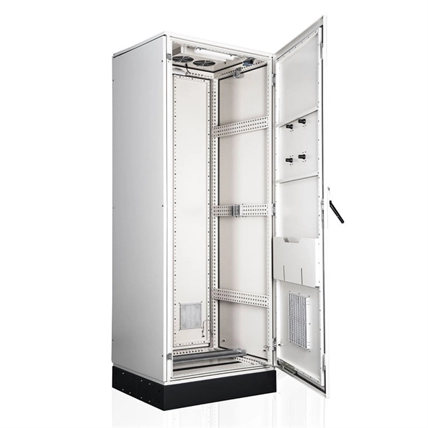
Low-voltage switchgear busbars are arranged to balance current-carrying capacity, thermal performance, mechanical strength, and safety, typically using horizontal main busbars with modular compartmentalization.Core Principles of Busbar ArrangementIn low-voltage switchgear, busbars serve as the main current-carrying path, distributing power from incoming feeders to outgoing circuits. The arrangement must ensure:Continuous current capacity without exceeding temperature rise limits.Short-circuit withstand strength to survive electrodynamic forces.Efficient space utilization to allow functional units and future expansion.Thermal management to prevent heat accumulation inside the enclosure . Horizontal busbars are commonly used as the main distribution path, often complemented by vertical busbars for connecting functional units. Standardized busbar widths and thicknesses are applied across different ratings, with adjustments in layering or quantity to handle higher currents .Busbar Types and MaterialsRigid busbars: Solid copper or aluminum bars, providing high mechanical strength and stability for main current paths.Flexible busbars: Thin copper layers or braided conductors, used for connections to breakers or where vibration/movement occurs.Flat busbars: Easy to install and dissipate heat efficiently.Tubular busbars: Hollow, lighter, and improve cooling in high-current applications.Laminated busbars: Thin conductors with insulation layers, reducing inductance and improving compactness . Busbars are typically made of high-conductivity copper, often tin-plated for corrosion resistance, and supported by arc-resistant, non-flammable materials like fiberglass-reinforced polyester DMC to provide mechanical strength and dielectric properties .Standards and ComplianceLow-voltage switchgear busbar arrangements must comply with IEC 61439 and related standards (e.g., BS EN 60439-1/2), which define:Temperature rise limits under rated current.Short-circuit withstand strength.Forms of internal separation (Form 1 to Form 4b) to segregate busbars, functional units, and terminals for arc fault containment and personnel protection .Verification methods including testing, calculation, or comparison with reference assemblies .Practical Arrangement StrategiesParallel busbars per phase: Often two busbars per phase and neutral for main and tee-off connections, ensuring sufficient current capacity and redundancy .Modular compartments: Functional units are separated to improve safety, heat dissipation, and maintenance access.Tee-off connections: Designed for easy connection to outgoing circuits, available in various ratings (e.g., 160A, 250A, 630A) to facilitate maintenance and system expansion .Heat management: Busbar geometry and spacing are optimized to allow natural convection and prevent hotspots .SummaryA well-designed low-voltage switchgear busbar system integrates horizontal main busbars, modular compartments, and standardized busbar sizes to achieve safe, reliable, and efficient power distribution. Compliance with IEC 61439 and related standards ensures thermal stability, mechanical integrity, and arc fault protection, while practical arrangements like parallel busbars and tee-off connections enhance maintainability and scalability .